Local Emission
Description
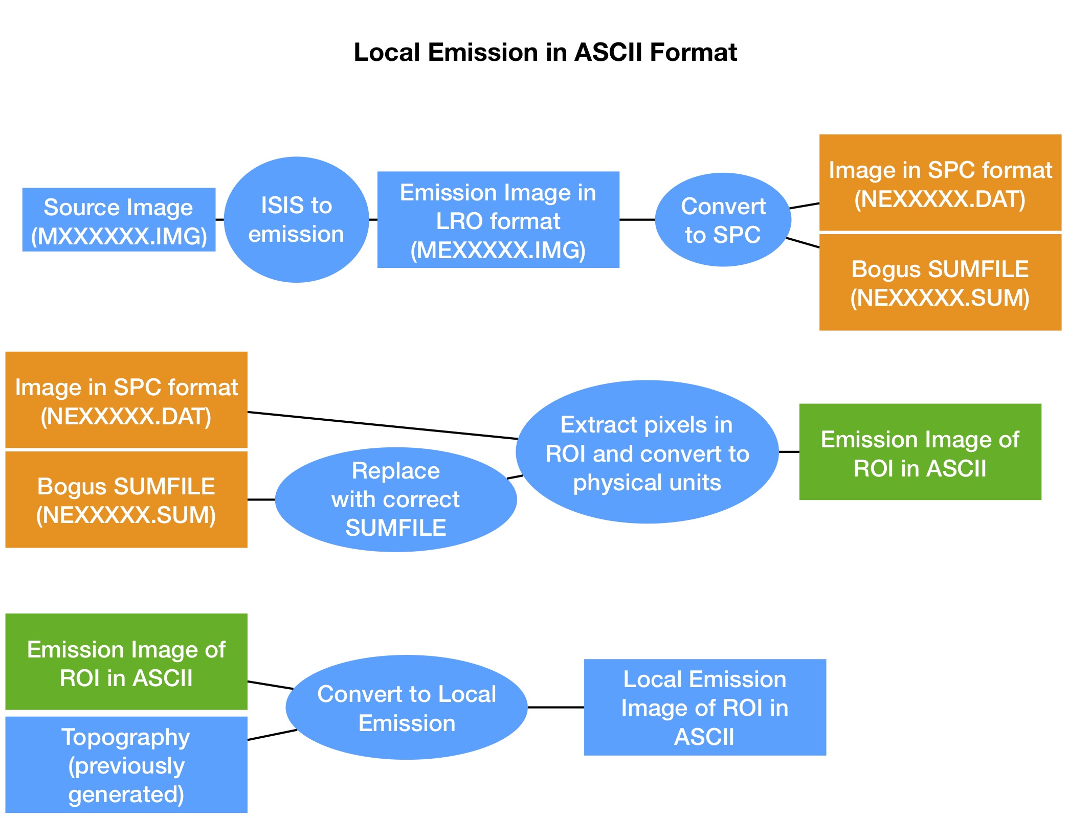
This is the process to generate local emission for each LROC NAC image. It requires the DTM to have already been generated. This is a circuitous process that involves ISIS and SPC and ends with an ASCII image.
Procedure
Overview
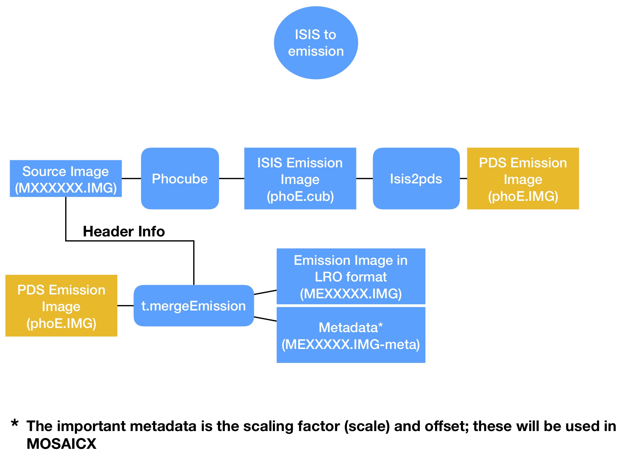
ISIS to Emission sub-block
More details can be found here ISIStoEmission
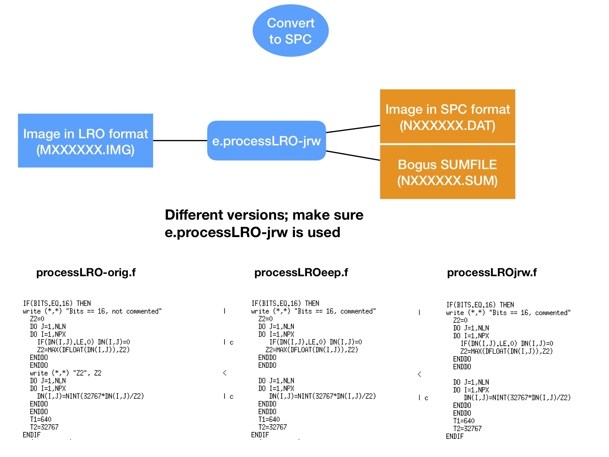
Convert LRO NAC emission image to SPC sub-block
The Fortran code used can be found here. processLROjrw.f
Replace with correct SUMFILES
- Copy the SUMFILE from the topography SPC directory to the “working” directory in the Cube generation directory. Nothing crazy here, but you will need to change the filename from NXXXXX.SUM to NEXXXXX.SUM (for emission) or NPXXXXX.SUM (for phase). For I/F, you can leave the filename the same.
- No need to change the contents of the SUMFILE, though if you want to keep the standard SUMFILE format, the first line (the SUMFILE name) should match the new filename. I don’t change the first line since it doesn’t affect the results.
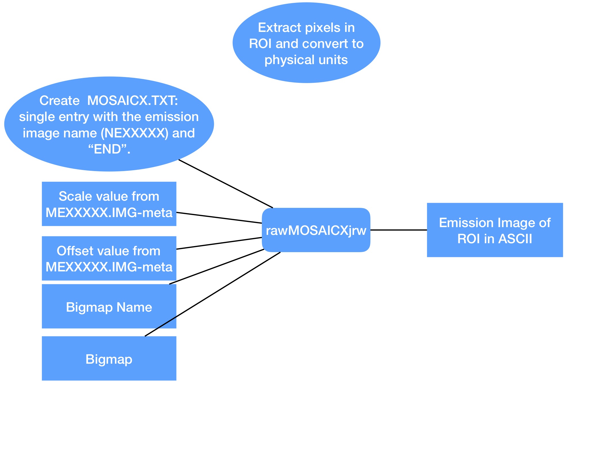
Extract Pixels in ROI
The Fortran program is found here. rawMOSAICXjrw.f
A wrapper to run MOSAICX is here. ||MOSAICX Emission Wrapper ||
Convert to Local Emission
- I have a program that needs a lot of setup for each image and bigmap. The base version is dumpMapEmiss.f, but I create a new file for each location on the Moon. I am only giving the overall idea here…
- Since LRO is a line scan, the angle between the surface and the s/c is always east or west, with no north or south component. Update dumpMapEmiss.f to include various parameters that solve for the local emission angle for each image. Since the emission image in ASCII format is essentially a “scalar” value (i.e. doesn’t include east or west), determining the parameters is a manual process that requires the user to determine if the s/c was east or west of the western portion of the bigmap. You also have to set a parameter which checks for an inflection point in the emission image in ASCII format. This step is required because for some of the images, the s/c to topography vector flips is east on the left side of the image and is west on the right side of the image, or vice versa. The flip occurs because the image is mostly nadir pointing.
- The program uses the DN from the emission image in ASCII format, along with the user defined east/west, and does vector addition with the normal of the topography at each pixel to determine the local emission angle. The program starts at the left edge of the bigmap and works right, checking for an inflection point in the emission image in ASCII format. Other special situations require additional parameters, such as when an image strip is diagonal with respect to the bigmap, such that the image strip only covers a portion of the left edge of the bigmap. When this happens it confuses the check for an inflection point, so an exception must be explicitly defined. There is almost certainly a more effective way to program the check for the inflection point so it doesn’t require so much manual massaging, but this is what I came up with in the allotted time.
Fortran code for Reiner Gamma 2 is here. dumpMapLRO_RG2.f
Finally, sometimes the output from MOSAICX gives low DN for a string of pixels (zero + the offset). If this low value is not correct (i.e. it is not low in the output from ISIS to Emission) then the DN can be interpolated from the surrounding pixels. This is done via dumpMapLRO_fixErrors.f


