Test11 K-R (JRW)
Aim and Objectives
Purpose of test: To determine the effect of sun zenith on the quality of the final solution produced by SPC when there is no s/c error (i.e. s/c position and pointing).
Methodology
Data
- Topography was generated by EP that had 20deg sloped boulders and regular simple craters.
- We chose to analyze a boulder near the center of the region created by EP.
- Image suite (below) of 2cm/px images.
Name |
Sun |
S/C Az |
S/C Zenith |
Test11K |
30 |
every 45 |
45 |
Test11L |
30 -30 |
every 45 |
45 |
Test11M |
-45, -45 |
every 45 |
45 |
Test11N |
30, 0, -30 |
every 45 |
45 |
Test11P |
45, 30, 0, -30, -45 |
every 45 |
45 |
Test11Q |
60, 45, 30, 0, -30, -45, -60 |
every 45 |
45 |
Test11R |
60, 30, -30, -60 |
every 45 |
45 |
Bigmaps
The following bigmaps were tiled/iterated and evaluated:
Starting topography defined from: START1 created at 20cm from REGION.MAP
Step |
GSD |
Overlap Ratio |
Q Size |
Width |
10cm-Tiling |
10 |
1.3 |
49 |
|
5cm-Tiling |
05 |
1.3 |
49 |
Iteration Parameters
Reset albedo/slopes: NO
Calculate Central Vector: YES
Differential Stereo: YES
Shadows: YES
Individual Results
Results and Discussion
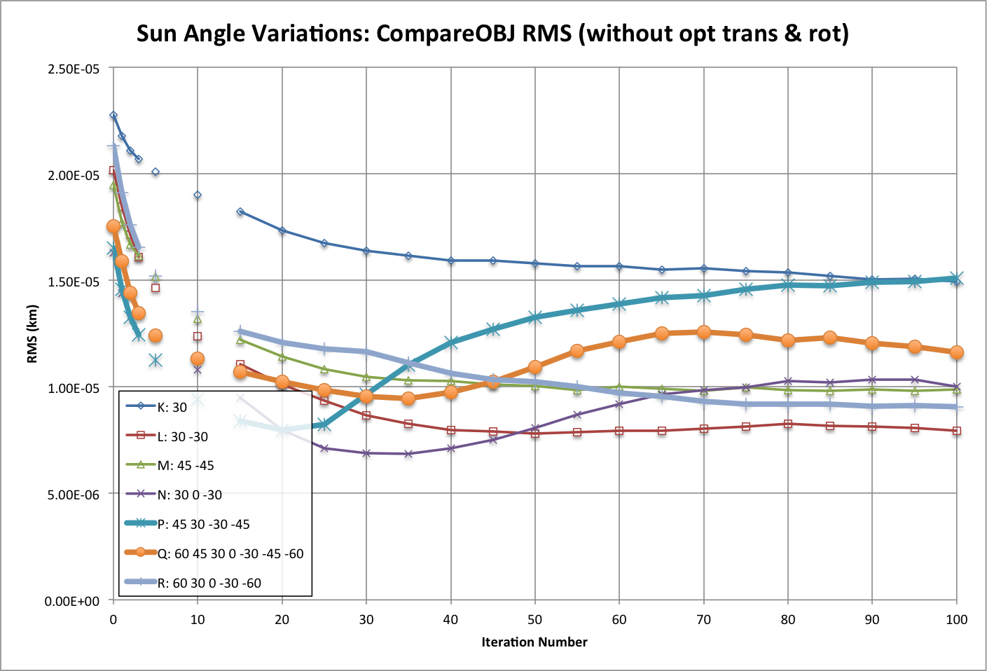
In all cases we were able to achieve an RMS less than the image resolution. A single sun angle performed worse than the rest by about a factor of 2. It isn't surprising that one sun angle did the poorest, but it is surprising that one sun angle did well. In fact, after 100 iterations it did as well as one of the other tests. Nonetheless, using a single sun angle during operations is not recommended. In many of the scenarios there appears to be a wobble to the RMS as you iterate. This is also surprising, but since the RMS is so low it would be more of a science project to understand why; it is not mission critical to learn why there is a wobble. Likewise, the RMS improves for awhile in all cases, then starts getting worse. And the number of iterations it takes before the RMS starts to increase is not predictable. Surprisingly, having more sun angles doesn't help the solutions very much. For example, Q has the most sun angles, and therefore took the longest time to iterate, but actually performed worse than some of the other cases. It appears that 2 or 3 sun angles is sufficient to obtain a good solution.
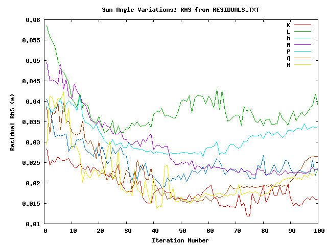
The value at the end of RESIDUALS.TXT doesn't seem to reflect the RMS very well. RESIDUALS is always greater than the RMS, and while L always has the worst RESIDUAL, the RMS is better than some of the others. Additionally, the test with only one sun angle (K) had a pretty good RESIDUAL, even though the CompareOBJ RMS was the worst of all tests. Bottom line: using RESIDUALS will have some meaning in a gross sense, but it can't be used to compare differences in quality at the fine scale. It has yet to be determined how we will use RESIDUALS. For most tests the RESIDUAL is greater than the image resolution, but less than the GSD. Standard procedure is to tile until the GSD is the same as the image resolution, which we didn't do in this case. So we can't take the results from RESIDUALS value in this test too far, but currently it seems that a good criteria for RESIDUALS is a value 3 times the image resolution. I say this because in other testing we found that increasing the GSD didn't have much affect on the CompareOBJ RMS. So if we were to tile until the GSD was the same as the image resolution I don't think the CompareOBJ would change much. There can't really be much "tighten up" either since none of the landmarks were throwing stars after the first couple iterations. In fact most landmarks had no error at all, so this is apparently the best SPC can do. After all, this whole test was done without s/c error. So we'll see how the RESIDUALS value of 3 times the image resolution holds up once we introduce s/c error.
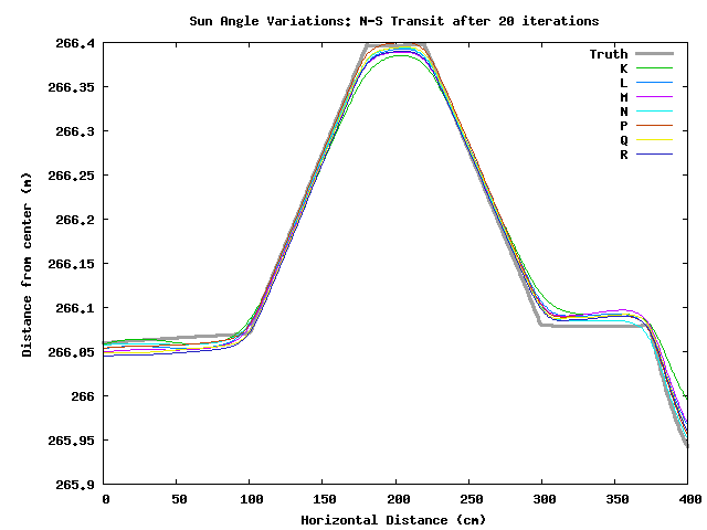
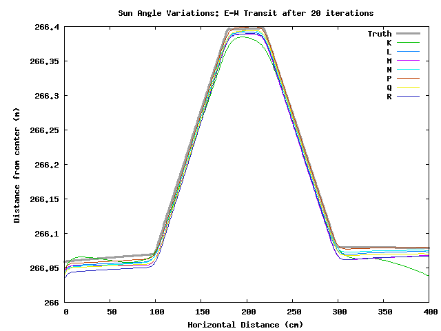
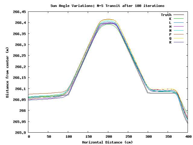
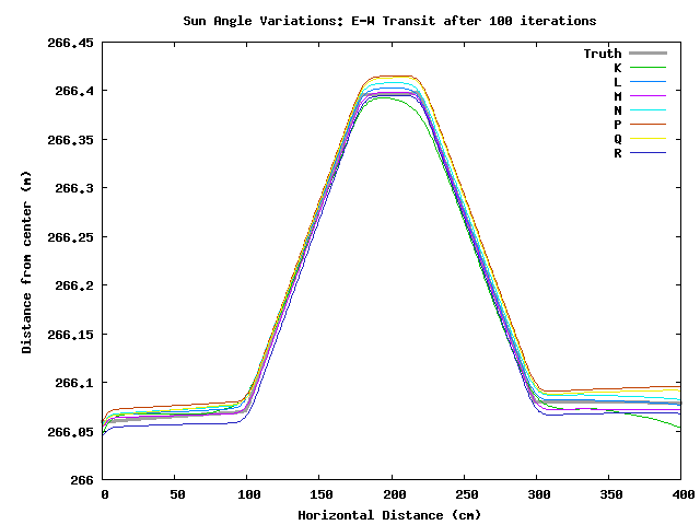
Looking at the transits of the different solutions, it appears that iterating after 20 times doesn't change the shape of the peak, it mostly just moves it around in space. Hence, I suspect the model-image to real-image correlations would be high, though I've not tested it.
There appears to be a N-S tilt in all these tests. Iterating improves the tilt, but in most cases the final heights are too high over much of the map. Click on the individual test results to see more details.
Conclusions and Recommendations
Two or three sun angles appears sufficient to obtain a good solution. Our test shows that +/-30degrees gives a better solution than +/-45degrees, but they are fairly similar. Adding a 0degree sun angle doesn't appear to improve things. Adding in 60degree angles actually makes the solution a bit worse in some cases.
From this test it appears that a RESIDUALS value that is less than 3 times the image resolution is sufficient to get ComapreOBJ RMS values less than the image resolution. However, we'll have to see what happens when we introduce s/c error.
Other
Tile seed
0.00010,49
g
i
a
y
.5
n
x
.025
0
a
b
n
XXXXXX
n
2
b
n
XXXXXX
u
1
v
2
e
a
0,60,.25,.25,0,3
1
0
3
n
0
y
1
0
1
n
0
y
0
c
.5
0
0
40
1
0
3
n
0
y
1
0
1
n
0
y
e
o
.5
0
a
u
1
0
0
40
2
8
2
.01
1
4
1, 2.5, 3
6
y
y
0
.025
30
0
u
1
v
1
1
0
1
n
0
y
u
1
0
0
40
1
0
2
n
0
y
1
0
1
n
0
y
e
o
.5
u
1
0
0
40
2
8
2
.01
1
4
1, 2.5, 3
6
y
y
0
.025
30
0
u
1
v
1
1
0
1
n
0
y
u
1
o
RECENT
y
1
o
RECENT
n
3
y
1, 3, 5 w
i
RECENT
n
n
v
1
u
1
#v
#4
o
RECENT
n
1
q
END
Iterate Seed
# This script performs two maplet iterations in parallel mode.
# It reinitializes slope and albedo.
# It recomputes maplet overlaps.
# It recomputes limb fits.
# It recomputes central maplet vector.
# Topography determination from slopes is conditioned by:
#   Initial topography,
#   Overlapping topography,
#   Shadowing,
#   Differential stereo,
#   Limb heghts.
# Dataless area slopes are set from the shape model.
#
# The script hides most of the screen output.  In order to obtain the
# full display replace H* by #H*.
#
# Modified 2011_12_31.  Header and comments added.
# Modified 2014_02_26.  Hide screen output added.
#
H*
x
.025
#
# Initialize slope and albedo.
#
#a
#y
#y
#
# Begin first iteration.
#
0
40
1
0
1
n
0
y
u
0
40
#
# Begin topo determination.
#
2
8                fill no data with shape slope
2                condition with existing topo
.01
7                condition with shadows
.025
1                condition with overlapping maps
4                condition with limbs
1, 2.5, 3
6                condition with differential stereo
y
0                begin integration
.025
15
0
u
1
0
2
n
0
y
1
0
1
n
0
y
u
#
# Begin second iteration.
#
0
40
1
0
1
n
0
y
u
0
40
#
# Begin topo determination.
#
2
8
2
.01
7
.025
1
4
1, 2.5, 3
6
y
0
.025
15
0
u
1
0
2
n
0
y
H*
1
0
1
n
0
y
H*
u
#
# Begin overlaps and limb fits.
#
o
RECENT
y
1
o
RECENT
n
3
y
1, 3, 5
#
# Central vector determination.
#
v
RECENT
q
END
