|
Size: 5768
Comment:
|
Size: 6511
Comment:
|
| Deletions are marked like this. | Additions are marked like this. |
| Line 18: | Line 18: |
Figure 2 Shows how equidistance image azimuth representation affects where CompareOBJ's RMS minimum occurs in the iterative process. Error bars were added to the line graph to show that the iteration where the minimum occurs is at most a distance of 4 from the value measured. The error bars basically are there to let the observer know that measurements were taken every 5 iterations. Also, a trend line was added to the figure to demonstrate where the RMS minimum occurrence would be for equidistance azimuthal representations not tested. It is important to note that the trans line selected is logarithmic because a logarithmic trend line gave the best correlation with data and it fell in within the error bars of all the data points. |
Test Over11 F/G/H/I/J Comparative Results
Line Graphs
The following two figures are line graphs that show measurements of CompareOBJ's calculated RMS with and without optimal rotation & translation at each iteration. Furthermore, figures 3 and 4 show CompMapVec's calculated RMS and the measured formal uncertainty at each iteration respectfully. A discussion of the observations are discussed below each figure. Note that iteration "0" is the tiling at 5 cm step.
Figure 1: CompareOBJ's Calculated RMS
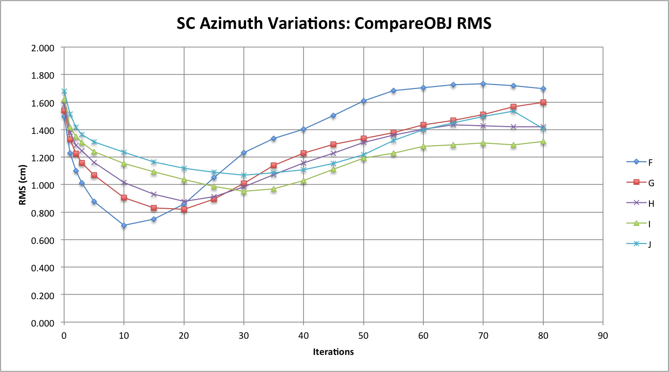
Comparing the CompareOBJ RMS between the Azimuth Variation Tests yielded very interesting results because one can clearly see the minimum CompareOBJ calculated RMS values obtained for each test. Test F has the lowest RMS minimum with it occurring the earliest and Test J has the greatest RMS with it occurring the latest. Furthermore, the other tests see to follow this trend where better azimuthal representation correlates to a lower CompareOBJ RMS minimum that occurs earlier while worse azimuthal representation correlates to a greater CompareOBJ RMS minimum that occurs later. The next to figures demonstrate this trend.
Before Discussing the next figures, one more observation that can be made from Figure 1 is that at the higher iterations Tests F, H, and I seem to converge (or at least seem steady), while Tests G and J do not converge. The RMS of Test G appears to still be increasing while the RMS of Test J hits an inflection point at iteration 75 and decreases. If Test J is disregarded, one could conclude that the better the azimuthal representation the greater the CompareOBJ RMS at higher iterations. However, since the sample is so small (because only 4 tests) the conclusion just made is not very strong. Furthermore, it is unknown whether Tests J's change in inflection at high iterations is common at azimuth representation above every 60 degrees.
Figure 2: CompareOBJ's Calculated RMS Minimum Occurrence
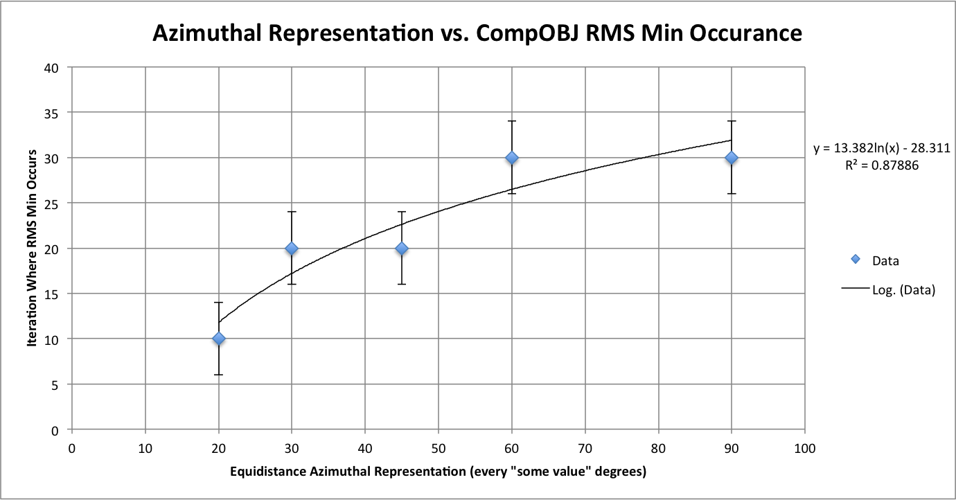
Figure 2 Shows how equidistance image azimuth representation affects where CompareOBJ's RMS minimum occurs in the iterative process. Error bars were added to the line graph to show that the iteration where the minimum occurs is at most a distance of 4 from the value measured. The error bars basically are there to let the observer know that measurements were taken every 5 iterations. Also, a trend line was added to the figure to demonstrate where the RMS minimum occurrence would be for equidistance azimuthal representations not tested. It is important to note that the trans line selected is logarithmic because a logarithmic trend line gave the best correlation with data and it fell in within the error bars of all the data points.
Figure 3: CompareOBJ's Calculated RMS Minimum Value
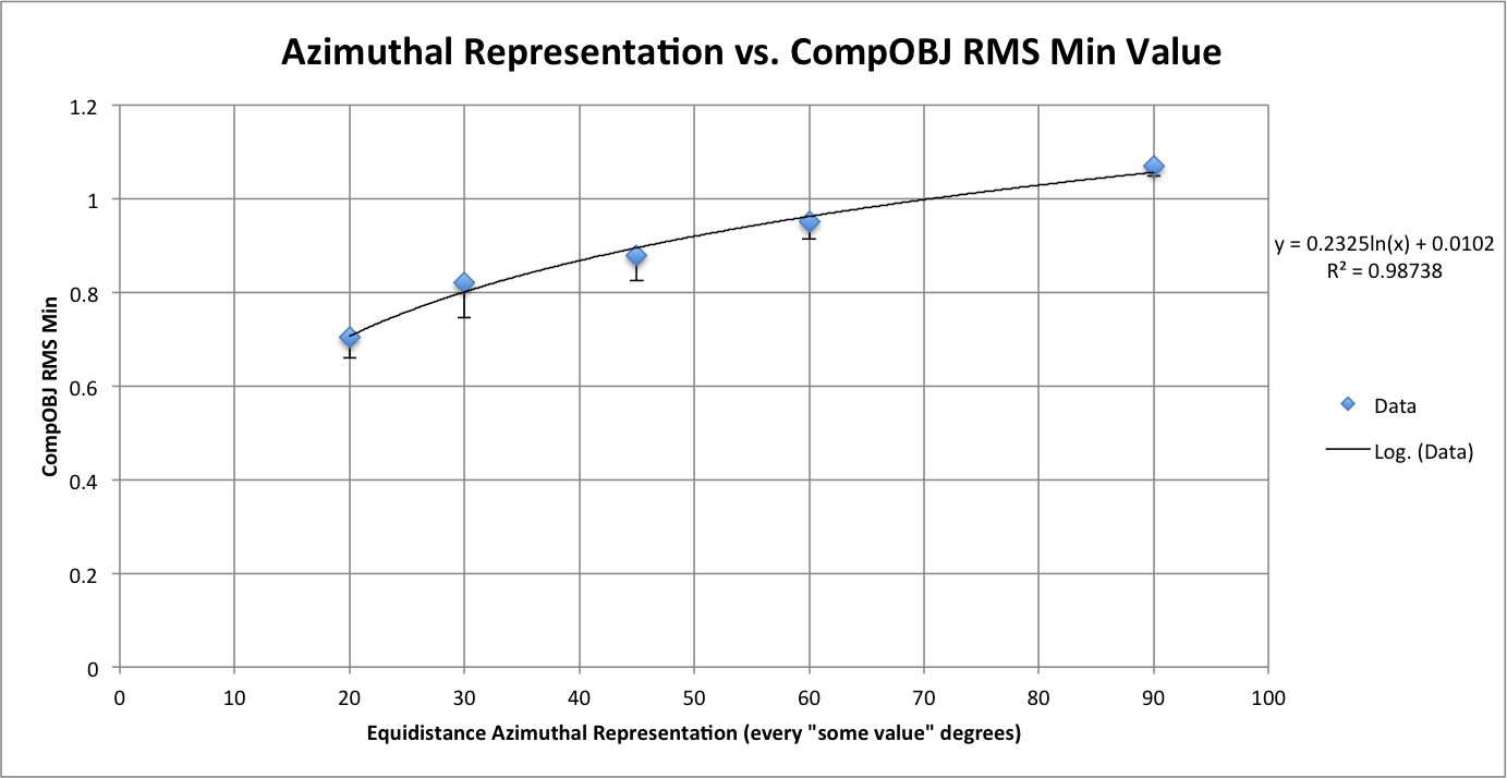
Figure 4: CompareOBJ's Calculated RMS With Optimal Rot. & Trans.
Figure 5: CompMapVec's Calculated RMS
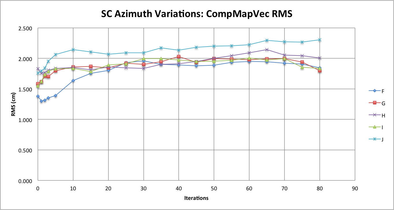
Figure 6: Measured Formal Uncertainty
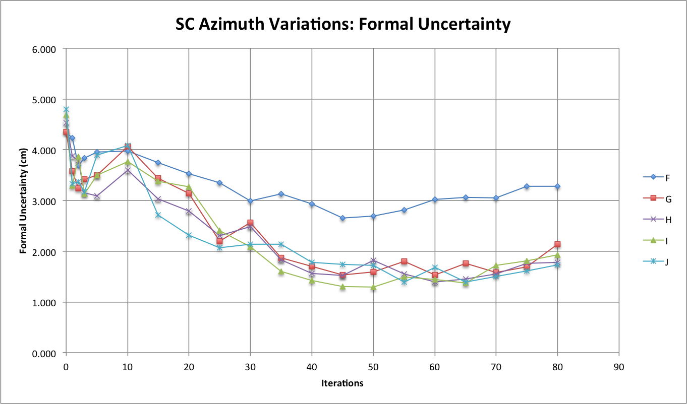
The observation that sticks out the most when comparing the formal uncertainty between the Azimuth Variations Tests is that at higher iterations the formal uncertainties for Tests G, H, I, and J seem to be hovering around one another while the formal uncertainty for Test F is about 1 cm greater than the formal uncertainty for all the other Azimuth Variation Tests. By looking at figure 1, one will also notice that CompareOBJ's calculated RMS for Test F is also the highest CompareOBJ calculated at relatively higher ( more than 30) iterations. This is interesting because Figure 3 shows CompMapVec's calculated RMS for Test F to be one of the lowest CompMapVec calculated RMS values at higher iterations. Thus, I do not think Figure 1 and Figure 3 can explain why Test F's formal uncertainty is so much higher than the formal uncertainty from all the other Azimuth Variation Tests at higher iterations when the RMS trend of those Tests are analyzed at higher iterations.
However, going back to the observations from Figure 1, it would seem that the minimum CompareOBJ RMS of Test F being the lowest and occurring the earliest my be able to explain why Test F's formal uncertainty is the greatest at greater iterations. Also, Figure 2 shows Test F's CompMapVec RMS to be the lowest at lower at iterations. Therefore, it appears that when the CompMapVec RMS and CompareOBJ RMS are relatively low, the formal uncertainty will be relatively high at greater iterations. The conclusion just made though will only occur when image azimuthal representation is better than some factor. From Figure 4, it appears that at that specific azimuthal representation factor, the formal uncertainty starts to be distinctly greater than when less azimuthal representation is present. Thus, it appears the azimuthal representation where the formal uncertainty is a lot greater is somewhere between every 30 degrees (Test G) and every 20 degrees (Test F).
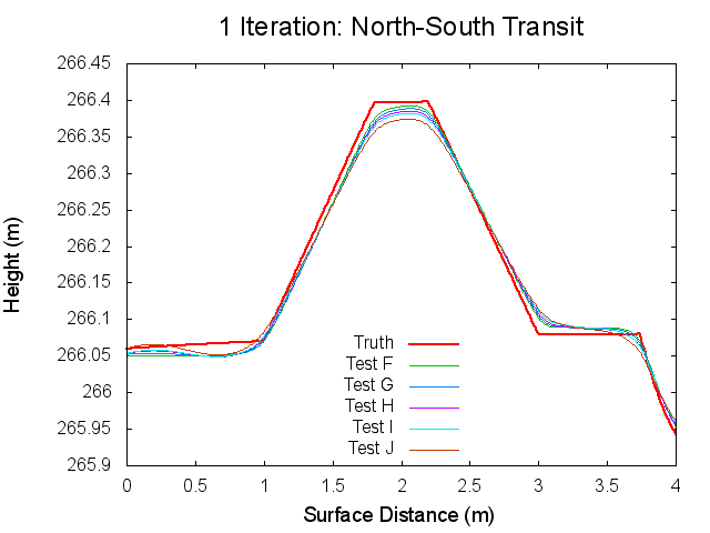
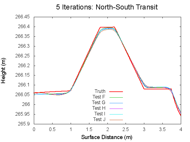
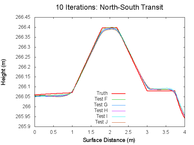
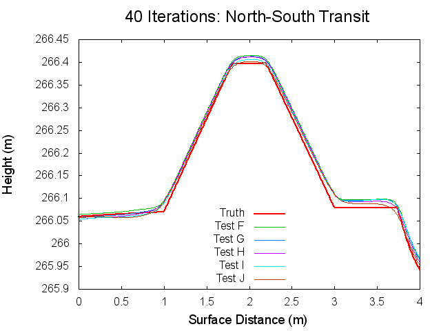
Traces: North to South
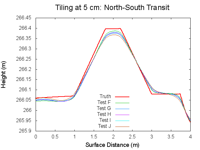
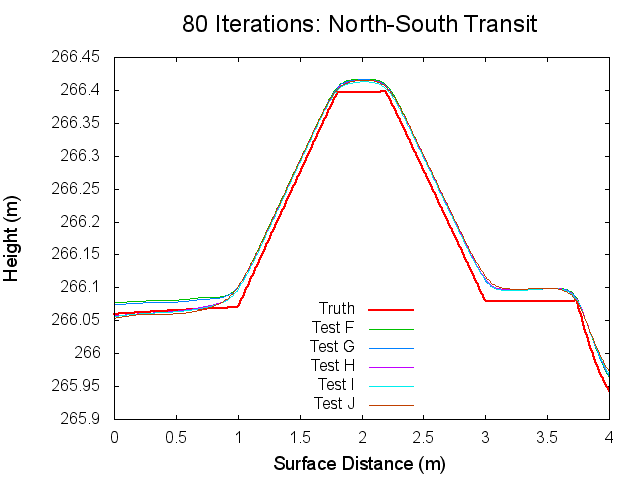
The following figures are topographical transits of the test bigmaps through the center (North to South) at various iterations throughout the SPC process.
Figures 7 through 12: North to South Traces of F/G/H/I/J Tests at various iterations
Traces: West to East
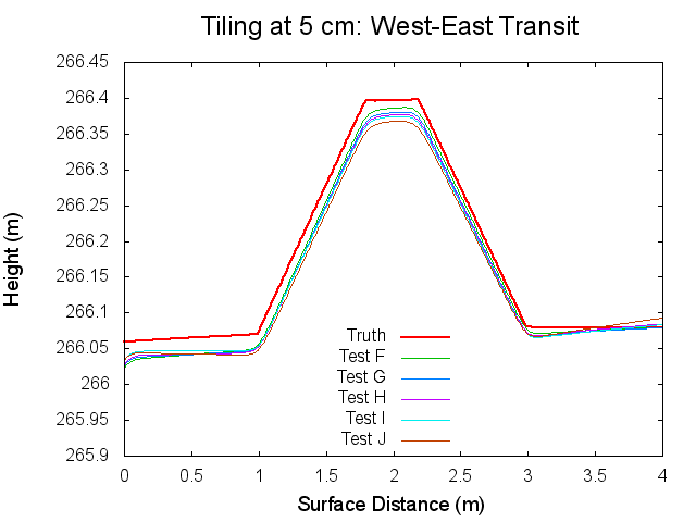
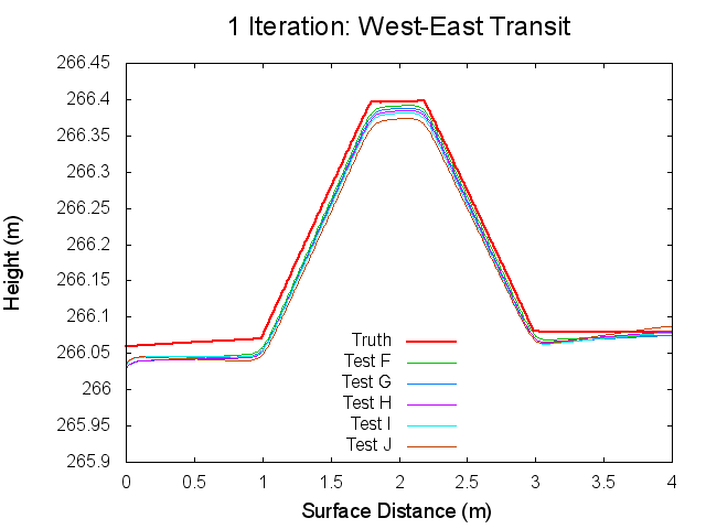
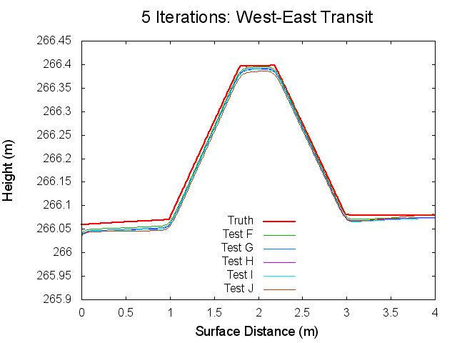
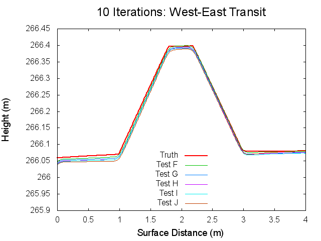
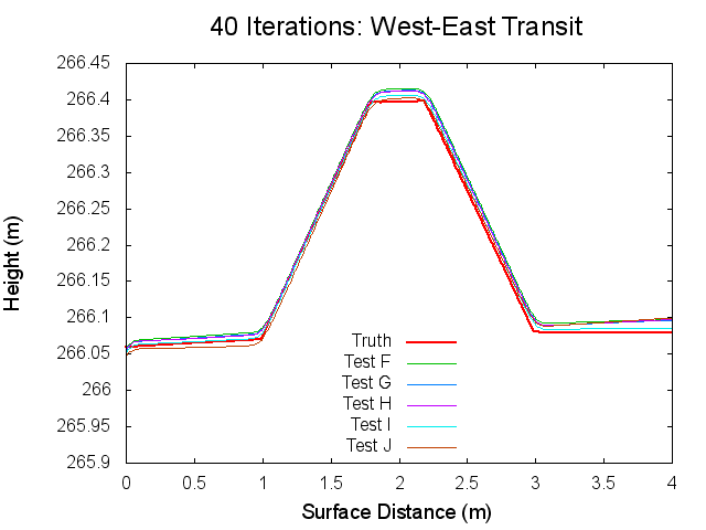
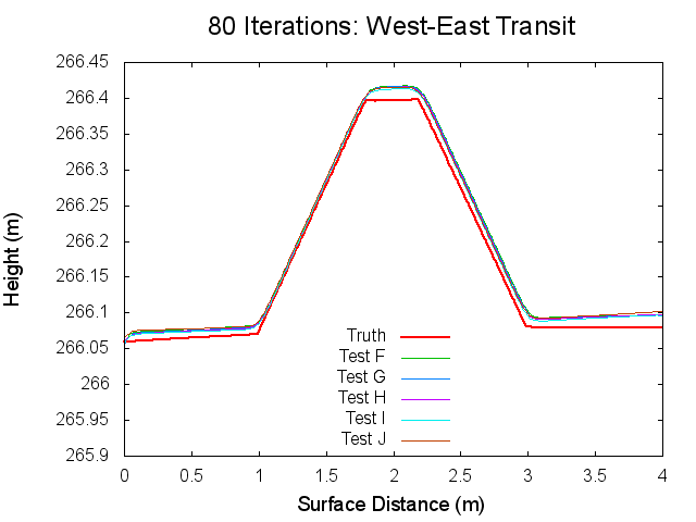
The following figures are topographical transits of the test bigmaps through the center (West to East) at various iterations throughout the SPC process.
Figures 12 through 17: West to East Traces of F/G/H/I/J Tests at various iterations
