|
Size: 6985
Comment:
|
Size: 6725
Comment:
|
| Deletions are marked like this. | Additions are marked like this. |
| Line 12: | Line 12: |
| * [[IMAGEFILES]]/ - A directory containing the image .DAT files. | |
| Line 25: | Line 24: |
| * [[MAPFILES]]/ - Directory that is also updated because the landmark vector in the header of the MAPFILE is also updated | * [[MAPFILES]]/ - This directory is also updated because the landmark vector in the header of the MAPFILE is also updated |
| Line 39: | Line 38: |
| ''''' /!\ Always back up your work before using geometry.''''' | ''''' {X} ALWAYS BACK UP YOUR WORK BEFORE USING GEOMETRY.''''' |
| Line 92: | Line 91: |
| * '''Spacecraft State''' - Position and orientation of spacecraft affects size and location of the body in an image. Errors are reflected by offsets of extracted image data from maplets for all maplets in the image. | * '''Spacecraft State''' - Position and orientation of spacecraft affects size and location of the body in an image. Errors are reflected IN offsets of extracted image data from maplets for all maplets in the image. |
| Line 98: | Line 97: |
| Line 99: | Line 99: |
Figure 00: Examples of Offset and Orientation Errors |
|
| Line 102: | Line 104: |
| * Global solution for camera pointing and body-fixed maplet location. | * Global solution for camera position and pointing and body-fixed maplet location. |
| Line 105: | Line 107: |
| * Nominal camera pointing and position | * Position of the landmark relative to the spacecraft |
| Line 107: | Line 109: |
| * Limb position * An initial starting object |
|
| Line 108: | Line 112: |
| * Nominal camera pointing * Nominal camera position * Limb position * Position of the landmark relative to the spacecraft * The observations before and after each observation |
|
| Line 109: | Line 118: |
| Solution of landmarks is also based on two additional constraints: limb height constraint and constraints from the shape model solution of camera position and pointing is also based on additional constraints image-to-image correlation and limb appearance in image other comments: option 1 solves for landmarks based on all 4 contributions, from position & pointing nominals, from relative landmark-to-landmark, from limbs and from shape model option 2 solves for camera position and pointing based on 4 constraints, from nominal position, pointing from landmarks from image-to-image correlation and from limbs |
|
| Line 126: | Line 122: |
| The typical use is a series of steps such as 120, 3 or more iterations. Assume we created some new landmarks. The above steps mean that we first use the apriori position & pointing information to solve for the landmarks, then, since there's some error in the a priori position and pointing inputs we use the landmarks to solve for position and pointing and so on until the corrections have converged, typically 3 iterations. However if we are in a situation where believe the landmarks are correct and the camera pointing/position are incorrect then we simply run option 2 only. This is what autoregister does, when we add new images to an existing landmark database. If we are in a scenario that we believe the camera position/pointing are correct and not the landmarks then we run option 1 only. Another consideration is the relative contribution of each constraint in the landmark/position/pointing solution via the additional weights in INIT_LITHOS.TXT, LMKWTS and PICWTS E.g., if the shape model is too coarse for the resolution of maps we are working with we may want to reduce the influence of the shape model as a constraint in the solution of the landmarks by reducing the value of WR in INIT_LITHOS.TXT If we believe that the S/C state is very well known compared to the landmarks we may want to not allow the landmarks to change the camera position much, by either using a very small position uncertainty in the nominals or in addition by reducing the value of WB in PICWTS |
The typical use is a series of steps such as 120, and 3 or more iterations. Assume we created some new landmarks. The above steps mean that we first use the a priori position and pointing information to solve for the landmarks. Then, since there is some error in the a priori position and pointing inputs we use the landmarks to solve for position and pointing and so on until the corrections have converged, typically 3 iterations. However, if we are in a situation where we believe that the landmarks are correct and the camera pointing/position are incorrect then we simply run option 2 only. This is what [[autoregister]] does, when we add new images to an existing landmark database. If we are in a scenario where we believe the camera position/pointing are correct and not the landmarks then we run option 1 only. Another consideration is the relative contribution of each constraint in the landmark/position/pointing solution via the additional weights in INIT_LITHOS.TXT, LMKWTS and PICWTS. For instance, if the shape model is too coarse for the resolution of maps we are working with, we may want to reduce the influence of the shape model as a constraint in the solution of the landmarks by reducing the value of WR in [[INIT_LITHOS.TXT]]. If we believe that the S/C state is very well known compared to the landmarks, we may want to not allow the landmarks to change the camera position much, by either using a very small position uncertainty in the nominals or in addition by reducing the value of WB in PICWTS. |
| Line 143: | Line 127: |
Figure 00: Illustration of Iterative Process for Updating Geometry |
geometry
Category B |
Version 3.0 |
 BACK UP YOUR WORK BEFORE RUNNING GEOMETRY!
Description
This program makes a surface by solving for the spacecraft position, spacecraft pointing, and landmark locations. This procedure iterates the solutions for camera pointing and landmark vectors sequentially.
Required Files
LMKFILES/ - A directory containing the full suite of landmarks.
PICTLIST.TXT - A list of picture names generated by make_sumfiles.
LMRKLIST.TXT - A list of the landmarks contained in the solution.
LMRKLIST1.TXT - A file containing default values to be read in by SPC toolkit.
MAPFILES/ - A directory containing the full suite of maplets.
INIT_LITHOS.TXT - A text file setting limits, definitions, and logicals for SPC.
SHAPE.TXT - The shape model stored in directory SHAPEFILES/.
SUMFILES/ - A directory containing the image .SUM files (updated solution image, S/C and camera information; lmrks and limbs).
Output Files
SUMFILES/ - Landmarks are added to the image's SUMFILE. Spacecraft/camera position/attitude are updated upon user acceptance of alignment shifts.
LMKFILES/ - Directory LMKFILES/ is updated to contain the image the user is working with.
MAPFILES/ - This directory is also updated because the landmark vector in the header of the MAPFILE is also updated
Optional Files
PICTLISTS.TXT - User-generated list of picture names.
 geometry will only use this file instead of PICTLIST.TXT if you specify it in INIT_LITHOS.TXT with GEOPIC='PICTLISTS.TXT'.
 LMRKLISTR.TXT - User-generated restricted list of landmark names.
 geometry will only use this file instead of LMRKLIST.TXT if you specify it in INIT_LITHOS.TXT with GEOMAP='LRMKLISTR.TXT'.
User Warning
 ALWAYS BACK UP YOUR WORK BEFORE USING GEOMETRY.
Using geometry
The inputs for geometry are:
input operation list - Use these values:
- 1: landmark vectors.
- 2: camera pointing, scobj
- 0: end.
enter number of iterations - Input desired number.
use limbs for pointing? (y/n) - Choose whether to use limbs in determining camera pointing.
continue? (y/n) - Choose whether to do it all over again.
Here are two annotated samples that show geometry inputs:
 GEOMETRY
 120<- do 1 followed by 2
 30 <- do them 30 times
 y  <- use limbs for pointing
 n  <- stop when done

 GEOMETRY
 20 <- do 2 only
 10 <- do it 10 times
 n  <- don't use limbs for pointing
 n  <- stop when done
The default is to do these operations for all landmarks in LMRKLIST.TXT and all images in PICTLIST.TXT.
If INIT_LITHOS.TXT contains a record
GEOPI='filename1'

or

GEOMAP='filename2'
then the files used are reduced. "filename1" is used instead of PICTLIST.TXT and "filename2" is used instead of LMRKLIST.TXT.
Additional Reference
Geometry Estimation Terms
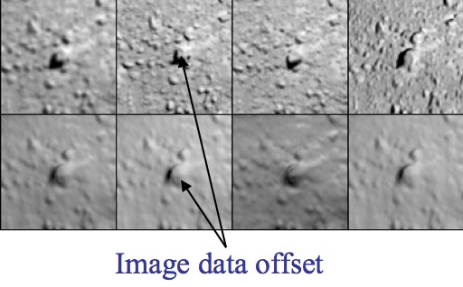
Spacecraft State - Position and orientation of spacecraft affects size and location of the body in an image. Errors are reflected IN offsets of extracted image data from maplets for all maplets in the image.
Control Point Location - An error in the body-fixed control point location is reflected by offsets of extracted image data for all images containing the maplets.
Rotation - An error in the transformation from inertial to body fixed frames is reflected in time-dependent offsets in extracted image data for all maplets in all images.
Differential Stereo - Errors in the maplet heights relative to the center are reflected by differential shifts of features within the extracted image data in addition to displacements from the maplets themselves.


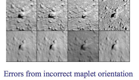
Figure 00: Examples of Offset and Orientation Errors
More Detailed Description of Geometry
- Global solution for camera position and pointing and body-fixed maplet location.
- Iterative process:
- Weighted least-squares solution of landmarks (control points) based on:
- Position of the landmark relative to the spacecraft
- Relative landmark-to-landmark location
- Limb position
- An initial starting object
- Weighted least-squares solution of camera position and pointing based on landmark location
- Nominal camera pointing
- Nominal camera position
- Limb position
- Position of the landmark relative to the spacecraft
- The observations before and after each observation
- Weighted least-squares solution of landmarks (control points) based on:
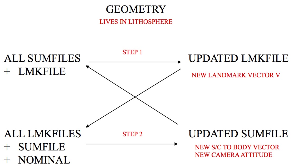
The output covariances from one iteration become the input covariances for the next iteration so the schematic for updating sumfiles, and lmkfiles, should include the update of their uncertainties.
The typical use is a series of steps such as 120, and 3 or more iterations. Assume we created some new landmarks. The above steps mean that we first use the a priori position and pointing information to solve for the landmarks. Then, since there is some error in the a priori position and pointing inputs we use the landmarks to solve for position and pointing and so on until the corrections have converged, typically 3 iterations. However, if we are in a situation where we believe that the landmarks are correct and the camera pointing/position are incorrect then we simply run option 2 only. This is what autoregister does, when we add new images to an existing landmark database. If we are in a scenario where we believe the camera position/pointing are correct and not the landmarks then we run option 1 only.
Another consideration is the relative contribution of each constraint in the landmark/position/pointing solution via the additional weights in INIT_LITHOS.TXT, LMKWTS and PICWTS. For instance, if the shape model is too coarse for the resolution of maps we are working with, we may want to reduce the influence of the shape model as a constraint in the solution of the landmarks by reducing the value of WR in INIT_LITHOS.TXT. If we believe that the S/C state is very well known compared to the landmarks, we may want to not allow the landmarks to change the camera position much, by either using a very small position uncertainty in the nominals or in addition by reducing the value of WB in PICWTS.

Figure 00: Illustration of Iterative Process for Updating Geometry
(Compiled by TC)
