spheremapsB
Category B |
Version 3.0 |
Description
This program transforms maplet data from DTM to common formats and map projections for export.
SpheremapB reads the Zmap files and makes the resulting map line by line, which is more robust than bigmap. It creates:
- a suite of data files for a bigmap (REFMAP)
- a raw (simple binary) file of a 2D matrix for the scaled albedo (sample_ALB) and the topography (DEM)
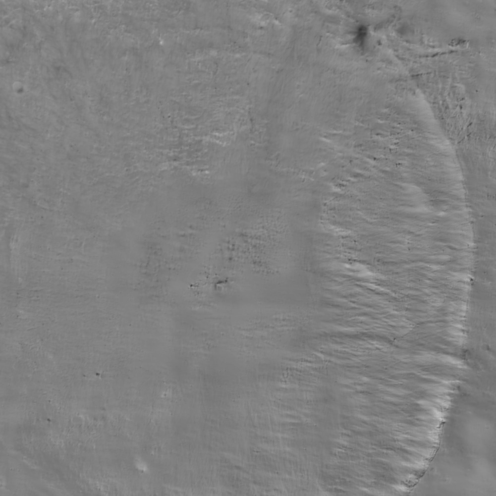
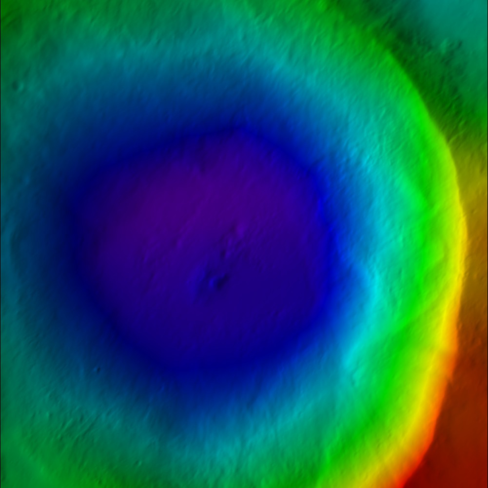
- images (pgm format) of the albedo, topography, and color scaled topography
Required Files
MAPFILES/ - a directory containing the full suite of maplets
MAPLIST.TXT - a file listing the map files. You must build this yourself.
- Note: You can only have 9,000 maplets in the file.
Output Files
<BIGMAP>_DTM.pgm - Bigmap pgm image file (grayscale)
<BIGMAP>_DTM.raw - Bigmap raw image file (simple binary)
<BIGMAP>_COL.ppm - Bigmap raw image file (colorized)
<BIGMAP>_ALB.pgm - Big albedo map pgm image file (grayscale)
<BIGMAP>_ALB.raw - Big albedo map raw image file (simple binary)
Using spheremapsB
The following sample shows the prompts and standard inputs for spheremapsB:
Note: "tolerance" below refers to how far away spheremapsB will look to find maplets. A value too big here may start grabbing maplets from the other side of the body.
  input ltd (deg), elon (deg), scale (km/px),
  half-sizes (px/ln), ref radius (km), tolerance (km)

 0, 0
 0.06250
 500, 500
 265
 50

  input map name

 ZN0000

 a. orthographic
 b. stereographic
 c. equirectangular

 c

  Enter reference latitude
 0


 a. 8  bit DTM
 b. 16 bit DTM

 a

 Enter i,j,h map shift (m) (eg map-lola)
   10.098592111467099        20.849462131360269
 0, 0, 0

 Fix hmin, hmax? (y/n)
 n

 Set max slope (deg)
 60

 Lat/Lon markings? (y/n)
 n
The following samples show outputs from spheremapsB for each of the identified elements:

Figure 00: Albedo Output from spheremapsB
 Figure 00: Color DTM Output from spheremapsB

Figure 00: Grayscale DTM Output from spheremapsB
Additional Reference
[From spheremapsB.f]
C     This procedure re-samples the surface vectors providid ba a set of
C     BIGMAPs onto a sphere with a radius characteristic of the body.  Id
C     does so one outputline at a time so that arbitrarily large maps can
C     be produced.
C
C     The procedure produces three types of map.  A simple digital
C     elevation map (DEM) that provides te height above (or below) the
C     reference sphere at each point in either 8- or 16-bit format, a
C     shaded relief map (color coded with shading), and a relative albedo
C     map.  This latter should be taken with a grain of salt, since the
C     albedo solution from SPC is quite crude.  The DEM and albedo map are
C     presented as both raw and as .pgm files, while the shaded relief is
C     a .ppm file.  The raw files are included because they are easier to
C     ingest into other systems such as ISIS.  The .pgm DEM file has a
C     header that includes the ancillary information for the projection.
C     It can be read by any text editor.
C
C     Three types of projection are recognized by spheremapsB.  Orthographic and
C     stereographis are usually used for polar projections while equirectangular
C     (cylindrical) is used for oher regions, including the global DEM.  The program
C     first asks for:
C
C          central latitude and east longitude in degrees,
C          the scale (km/px),
C          the half-sizes in pixel and line directions,
C          ref radius (km),
C          tolerance (km)
C
C     The last entry is a search limit in case one of the maps has some bad data in it
C     and is displaced too far from the expected height.
C
C     The user then enters a name for the map, MAPNM.  Note that his does not have to be
C     6-characters.  Then the user chooses the projection:
C
C          a. orthographic
C          b. stereographic
C          c. equirectangular
C
C     If a or b is chosen, the user enters a cone angle.  For example, if the cone angle
C     is 70 degrees and the central latitude is 90 degrees, then the map will cover from
C     20 degrees north to the pole.  If c is chosen, the user is asked for a reference
C     latitude.  At that latitude, the pixels are square at a resolution equal to the
C     scale chosen above.  Poleward, the pixels are at higher resolution in the east-
C     west direction.  If the longitude range of the plot is to be DLON and Q is the
C     half-size in pixels in the east-west direction, then
C
C          2*Q*scale=R0*cos(Rlat)*DLON*pi/180
C
C     In particular, if we want a global DEM at, say 32 pixels per degree then DLON=360,
C     2*Q=360*32 and if Rlat=0 then scale=R0*pi/32*180.
C
C     After deciding on the type of projection and its parameters, the user is asked:
C
C          a. 8  bit DTM
C          b. 16 bit DTM
C
C     where if the latter is chosen the data will be "unsigned short" (MSB).  The next
C     choice is:
C
C          Fix hmin, hmax? (y/n)
C
C     If 'n' is chosen, the minimum and maximum heights will be those found for the
C     entire map.  On occasion,  especially if multiple maps are used to cover the body,
C     we want to use the same values for all maps and if ''y is chosen we enter those
C     values next.
C
C          Set max slope (deg)
C
C     The shaded relief map MAPNM_COL.ppm has both color coded heights and slopes
C     determined by pixel differencing so the maps appear to be illuminated from the
C     left.  The maximum slope, usually set to 45 degrees, sets the scale for the
C     apparent illumination.   A final choice is:
C
C          Lat/Lon markings? (y/n)
C
C     If 'y' is chosen, the user inputs spacings for lines of constant latitude and longitude
C     to be marked in white on the MAPNM_COL.ppm.
C
C     The MAPNM_DEM.pgm file has a header that includes ancillary information for the
C     projection.  For equirectangular projection the header looks like:
C
C          P5
C          #PROJECTION = EQUIRECTANGULAR
C          #REFERENCE RADIUS =         255.00000
C          #REFERENCE LATITUDE =         0.00000
C          #      -90.0000000464        0.0000000000       90.0000000464   MN, CT, MX LAT
C          #     -180.0000000928        0.0000000000      180.0000000928   MN, CT, MX LON
C          #               17281                8641                       IMAX, JMAX
C          #    0.9272061656D-01    0.1235028039D-02                       SCL, HTSCL
C          #   -0.4309964495D+02    0.3783668255D+02                       HTMIN, HTMAX
C          #    0.2550000000D+03    0.0000000000D+00    0.0000000000D+00   VLM
C          #    0.0000000000D+00    0.0000000000D+00   -0.1000000000D+01   UX
C          #   -0.0000000000D+00    0.1000000000D+01    0.0000000000D+00   UY
C          #    0.1000000000D+01    0.0000000000D+00    0.0000000000D+00   UZ
C          17281 8641
C          65535
C
C     where the lines without # specify the .pgm format.  For orthographic and stereographic
C     projections, the heaer looks like:
C
C          P5
C          #PROJECTION = STEREOGRAPHIC
C          #REFERENCE RADIUS =         250.00000
C          #               10401               10401                       IMAX, JMAX
C          #    0.1000000000D+00    0.1235079957D-02                       SCL, HTSCL
C          #   -0.3810336140D+02    0.4283636848D+02                       HTMIN, HTMAX
C          #    0.0000000000D+00    0.0000000000D+00    0.2500000000D+03   VLM
C          #    0.1000000000D+01    0.0000000000D+00    0.0000000000D+00   UX
C          #    0.0000000000D+00    0.1000000000D+01    0.0000000000D+00   UY
C          #    0.0000000000D+00    0.0000000000D+00    0.1000000000D+01   UZ
C          10401 10401
C          65535
JRW Notes after further testing: SCL is the distance in km you entered in for scale (i.e. the third entry after lat/elon). HTSCL is determined by taking the total distance from HTMIN to HTMAX and dividing by the number of bits (256 for 8-bit and 65536 for 16-bit)
(compiled by JRW from material by EEP)
Example
Target |
Sample Files |
Bennu |
Known Issues
Note: You can only have 9,000 maplets in the MAPLIST.TXT. The program will crash if you have more than 9,000.
