|
Size: 10578
Comment:
|
Size: 9878
Comment:
|
| Deletions are marked like this. | Additions are marked like this. |
| Line 2: | Line 2: |
| Line 4: | Line 3: |
| Line 9: | Line 7: |
| === Required Files === | === Required Files === |
| Line 26: | Line 24: |
| . ''''' /!\ To undo all changes since the last quit, you must select 'n' from the Main Menu.''''' . ''''' /!\ Since the SUMFILE is updated in realtime, an uncontrolled exit from '''register''' will result in the SUMFILE remaining modified.''''' |
|
| Line 27: | Line 27: |
| ''''' /!\ To undo all changes since the last quit, you must select 'n' from the Main Menu.''''' ''''' /!\ Since the SUMFILE is updated in realtime, an uncontrolled exit from '''register''' will result in the SUMFILE remaining modified.''''' ------------ |
---------- |
| Line 33: | Line 29: |
'''register''' provides an initial estimate for the spacecraft state (camera pointing and s/c-object vector) by aligning an image with a known object - either the shape model, a high resolution map or another (already registered) image. |
'''register''' provides an initial estimate for the spacecraft state (camera pointing and s/c-object vector) by aligning an image with a known object - either the shape model, a high resolution map or another (already registered) image. |
| Line 41: | Line 36: |
1. Enter the image name as stored in [[IMAGEFILES]]. . (i) ''Some versions of [[process_fits]] will make some changes to the filename, so it may not be the "original" name.'' |
1. Enter the image name as stored in [[IMAGEFILES]]. . (!) ''Some versions of [[process_fits]] will make some changes to the filename, so it may not be the "original" name.'' |
| Line 50: | Line 44: |
| Line 52: | Line 45: |
| Line 61: | Line 53: |
1.#3 Enter the scale in km. The basic display for REGISTER is 600x600 pixels. |
1.#3 Enter the scale in km. The basic display for REGISTER is 600x600 pixels. |
| Line 66: | Line 57: |
| Line 70: | Line 62: |
| Line 82: | Line 73: |
| (i) The display and the arrays of image and reference data are not the actual imaging data' instead, they are that data projected on a "substrate". When you are just starting processing and looking at low-resolution images of the body, the substrate is simply a plane through the body center oriented parallel to the camera's focal plane. This flat 'f' substrate is the default value. Once a decent shape model is obtained and the images cover a small fraction of the body's surface, the substrate is taken to be that surface itself, either in the form of the shape 's' or a high-resolution map 'm'. In this case, the topography is represented as a DTM whose reference plane is the same as the flat substrate with heights in the negative camera bore sight direction. Note that if the reference is also an image, this data is projected on the same substrate as the image being registered. |
. (!) The display and the arrays of image and reference data are not the actual imaging data' instead, they are that data projected on a "substrate". When you are just starting processing and looking at low-resolution images of the body, the substrate is simply a plane through the body center oriented parallel to the camera's focal plane. This flat 'f' substrate is the default value. Once a decent shape model is obtained and the images cover a small fraction of the body's surface, the substrate is taken to be that surface itself, either in the form of the shape 's' or a high-resolution map 'm'. In this case, the topography is represented as a DTM whose reference plane is the same as the flat substrate with heights in the negative camera bore sight direction. Note that if the reference is also an image, this data is projected on the same substrate as the image being registered. |
| Line 97: | Line 87: |
| 8. Change substrate | 8. Change substrate |
| Line 106: | Line 96: |
| Line 111: | Line 100: |
| '''Options 3''', '''4''' and '''6''': Make changes to the .SUM file in camera pointing and/or cross line-of sight scobj, camera twist and s/c range, respectively. | '''Options 3''', '''4''' and '''6''': Make changes to the .SUM file in camera pointing and/or cross line-of sight scobj, camera twist and s/c range, respectively. |
| Line 113: | Line 102: |
| '''Option 3''': This is the most often used option. . The new image is on the left or in red. Values entered (delta x, delta y) are the number of pixels by which the image will be shifted (as per the current scale). |
'''Option 3''': This is the most often used option. |
| Line 116: | Line 104: |
| (i) This isn't the same as moving the "window" as in [[lithos]]; instead, it updates the image's camera position and pointing. | . The new image is on the left or in red. Values entered (delta x, delta y) are the number of pixels by which the image will be shifted (as per the current scale). . (!) This isn't the same as moving the "window" as in [[lithos]]; instead, it updates the image's camera position and pointing. |
| Line 126: | Line 115: |
| If you respond Y, autocorrelate estimates the offset between the image and the reference. The three values displayed in the standard output are the delta x (pixels), delta y (lines), and the correlation score. | |
| Line 127: | Line 117: |
| If you respond Y, autocorrelate estimates the offset between the image and the reference. The three values displayed in the standard output are the delta x (pixels), delta y (lines), and the correlation score. * If the correlation gives a good match (greater than a preset limit, default=0.25), autocorrelate will shift the image and go back to the menu. * Otherwise, autocorrelate will ask for a manual input. * The preset limit can be changed with '''Option c'''. |
* If the correlation gives a good match (greater than a preset limit, default=0.25), autocorrelate will shift the image and go back to the menu. * Otherwise, autocorrelate will ask for a manual input. * The preset limit can be changed with '''Option c'''. |
| Line 136: | Line 125: |
| '''Option b''': Allows a flag to be set on the image that will enable its brightness variations to be used to determine topography but keeps it from participating in the geometry solution for the landmark vector. This is used to keep Mariner 10 images of Mercury, which have questionable nominals, from messing up the vector but still, with their sometimes unique sun angles, helping with the topography determination. | '''Option b''': Allows a flag to be set on the image that will enable its brightness variations to be used to determine topography but keeps it from participating in the geometry solution for the landmark vector. This is used to keep Mariner 10 images of Mercury, which have questionable nominals, from messing up the vector but still, with their sometimes unique sun angles, helping with the topography determination. |
| Line 151: | Line 140: |
| '''Accept shift?''': Note that the shift has already been applied (the SUMFILE is updated in real time). | |
| Line 152: | Line 142: |
| '''Accept shift?''': Note that the shift has already been applied (the SUMFILE is updated in real time). | |
| Line 155: | Line 144: |
| '''Update/Create rotation history file?''': Always enter 'n'. The rotation history file was introduced to keep track of pointing errors in Clementine data during Lunar orbits in an attempt to quantify systematic shifts. | ''Update/Create rotation history file?''': Always enter 'n'. The rotation history file was introduced to keep track of pointing errors in Clementine data during Lunar orbits in an attempt to quantify systematic shifts. |
| Line 157: | Line 146: |
| '''Update nominal file?''': Usually enter 'n'. Rarely, you may want to set the nominal file equal to the .SUM solution. | ''Update nominal file?''': Usually enter 'n'. Rarely, you may want to set the nominal file equal to the .SUM solution. |
| Line 160: | Line 149: |
| Line 162: | Line 151: |
| ~/bin/register | }}} Here is a sample showing registering an image with a shape: |
| Line 164: | Line 154: |
| input 12-character picture name. q to quit. N110751047R REFERENCE MAP = ZS0426 Input reference s. SHAPE i. IMAGE m. MAP m Input REFNM TSI003 enter scale (km/px) .6118483 0. Quit 1. Change scale 2. Global shift 3. Shift unknown (LEFT/RED) image 4. Rotate unknown (LEFT/RED) image 5. Change reference 6. Change RANGE of (LEFT/RED) image 7. Revert to nominal 8. Change substrate (s) 9. Change pole a. Turn off bkg b. Turn off image for Vlm c. Change correlation limit = 0.25 d. Fix scobj e. Fix pointing t. Tuck picture Current picture = N110751047R Current reference = TSI003 }}} Here is a sample showing registering an image with a shape: {{attachment:register_AlignsNewImage.jpg||width=600}} |
{{attachment:register_AlignsNewImage.jpg||width="600"}} |
| Line 205: | Line 158: |
| {{attachment:register_AlignsNewBigmaps.jpg||width=600}} | {{attachment:register_AlignsNewBigmaps.jpg||width="600"}} |
| Line 207: | Line 160: |
| {{attachment:register_example.jpg||width=600}} | {{attachment:register_example.jpg||width="600"}} |
| Line 210: | Line 163: |
| ''(Compiled by DL)'' CategoryPrograms Based on [[http://sbib.psi.edu/wiki_ext/refman.pdf|SPOC v3.02A PDF]]/LITHOSPHERE/REGISTER.f File Reference |
''(Compiled by DL)'' CategoryPrograms Based on [[http://sbib.psi.edu/wiki_ext/refman.pdf|SPOC v3.02A PDF]]/LITHOSPHERE/REGISTER.f File Reference |
register
Description
This program is used to register (add and align) new images to existing maplets.
register cross-correlates an image with existing data to update the knowledge of the spacecraft position/attitude. register is limited to 2 degrees of freedom.
Required Files
IMAGEFILES/ - a directory containing the image .DAT files
NOMINALS/ - a directory containing the image .NOM files (starting solution image, S/C and camera information)
SUMFILES/ - a directory containing the image .SUM files (updated solution image, S/C and camera information, lmrks and limbs)
MAPFILES/ - required for comparison with a reference map
SHAPEFILES/ - required for comparison with a shape model
Optional Files
make_scriptR.seed - for batch processing using make_scriptR
Output Files
NOMINALS/ - If you select the option to update the NOMINAL file, starting S/C and camera information will be updated (an option not typically selected)
SUMFILES/ - S/C and camera information are updated as image shifts are made. You can discard these changes upon quit.
- TEMPFILE.pgm - A side by side view of the image (left) and the reference (right)
- TEMPFILE.ppm - A red/cyan composite of the two items (red is image, cyan is reference)
User Warnings
 To undo all changes since the last quit, you must select 'n' from the Main Menu.
  Since the SUMFILE is updated in realtime, an uncontrolled exit from register will result in the SUMFILE remaining modified.
Using register
register provides an initial estimate for the spacecraft state (camera pointing and s/c-object vector) by aligning an image with a known object - either the shape model, a high resolution map or another (already registered) image.
The following shows the inputs and outputs of the program:
input 12-character picture name. q to quit.
Enter the image name as stored in IMAGEFILES.
 Some versions of process_fits will make some changes to the filename, so it may not be the "original" name.
 s = shape
 i = reference image
 m = reference map
- Enter the object to align with.
- s = shape - to use the current shape model
- i = image - select an already registered image; you will be prompted for an image name
- m = map - use a maplet/bigmap; you will be prompted for a map name
If you enter 0 for the map name, the program will search a set of "Zmaps" for the one most likely to overlap the image. Maps are only used after a detailed shape model and high-resolution maps have been constructed. At that time we are registering new images for navigation or improving the topography.
enter scale (km/px)
- Enter the scale in km. The basic display for REGISTER is 600x600 pixels.
- For example, if the body is 500 m across and the scale is entered at 5 m (.005), the image will be 100 pixels across in the display.
The output will look like this:
 gc TEMPFILE.pgm
 gc TEMPFILE.ppm
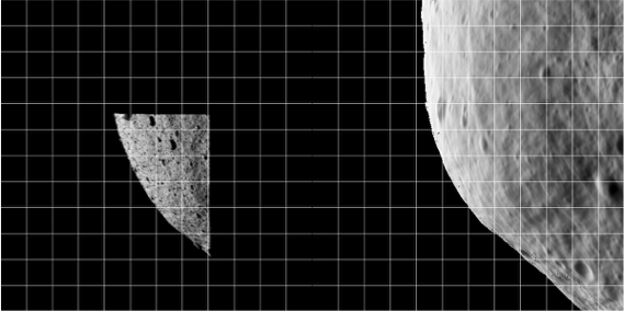
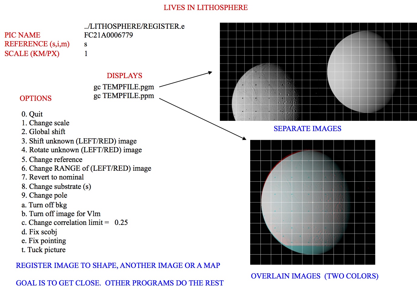
- TEMPFILE.pgm - A side by side view of the new image (left) and the reference (right)
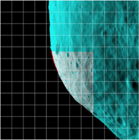
- TEMPFILE.ppm - A red/cyan composite of the two items (new is red, cyan is reference)
Here is a sample TEMPFILE.pgm file image:

Here is a sameple TEMPFILE.ppm file image:

 The display and the arrays of image and reference data are not the actual imaging data' instead, they are that data projected on a "substrate". When you are just starting processing and looking at low-resolution images of the body, the substrate is simply a plane through the body center oriented parallel to the camera's focal plane. This flat 'f' substrate is the default value. Once a decent shape model is obtained and the images cover a small fraction of the body's surface, the substrate is taken to be that surface itself, either in the form of the shape 's' or a high-resolution map 'm'. In this case, the topography is represented as a DTM whose reference plane is the same as the flat substrate with heights in the negative camera bore sight direction. Note that if the reference is also an image, this data is projected on the same substrate as the image being registered.
Main Menu
register main menu looks like this:
 0. Quit
 1. Change scale
 2. Global shift
 3. Shift unknown (LEFT/RED) image
 4. Rotate unknown (LEFT/RED) image
 5. Change reference
 6. Change RANGE of (LEFT/RED) image
 7. Revert to nominal
 8. Change substrate
 9. Update nominal and quit
 a. Toggle bkg
 b. Toggle image for Vlm
 c. Change correlation limit
 d. Fix/Unfix scobj
 e. Fix/Unfix pointing
 t. Tuck picture
Options 1, 5 and 8: Allow you to change the scale, reference object and substrate, respectively.
Option 2: Sometimes when trying to align an image to a reference, the entire display is off center. 'Option 2' moves both the image and reference displays by the same amount so that you can more conveniently align them, usually at smaller scale. This option only changes the user's point of view, not the image's location.
Options 3, 4 and 6: Make changes to the .SUM file in camera pointing and/or cross line-of sight scobj, camera twist and s/c range, respectively.
Option 3: This is the most often used option.
- The new image is on the left or in red. Values entered (delta x, delta y) are the number of pixels by which the image will be shifted (as per the current scale).
 This isn't the same as moving the "window" as in lithos; instead, it updates the image's camera position and pointing.
- After you enter option 3, you will input responses like these:
 Autocorrelate? (y/n)
y
        0.00000        0.00000        0.27302
 Enter px/ln IMAGE shift
If you respond Y, autocorrelate estimates the offset between the image and the reference. The three values displayed in the standard output are the delta x (pixels), delta y (lines), and the correlation score.
- If the correlation gives a good match (greater than a preset limit, default=0.25), autocorrelate will shift the image and go back to the menu.
- Otherwise, autocorrelate will ask for a manual input.
The preset limit can be changed with Option c.
Option 7: Populates the working .SUM file. This is sometimes a bailout procedure used the .SUM file is screwed up in some way. However, option 9 lets you save the current result as the nominal without changing the .SUM file from its original value. If for example, the spacecraft range is out to lunch (as it was on Hayabusa), the working .SUM file can be populated with the nominal, a change made to the range with option 6, and the new nominal saved with option 9.
Option a: When correlating small images to a nominal shape, we want to use all the data, so the space off the body counts just as much as the body itself. 'Option A' wakes up with a "background" turned on so that this correlation can be performed. Entering 'a' toggles this background off, so that only the common topography is correlated between the image and the reference object.
Option b: Allows a flag to be set on the image that will enable its brightness variations to be used to determine topography but keeps it from participating in the geometry solution for the landmark vector. This is used to keep Mariner 10 images of Mercury, which have questionable nominals, from messing up the vector but still, with their sometimes unique sun angles, helping with the topography determination.
Option c: Allows you to change the autocorrelation limit (default=0.25).
Options d and e: When an image shift has been determined, either manually or through autocorrelation, the camera pointing and spacecraft-object (scobj) vector in the .SUM file are changed in a manner weighted by their respective sigmas in the nominals (.NOM) file. If you want to keep one or the other unchanged, use the 'd' or 'e' option to fix it.
Option t: Allows an image to be tucked so it will not participate in the SPC process at all. It could be tucked from LITHOS, but it often happens that as REGISTER is used to cycle through new images, problems are easily seen and dealt with immediately.
0. Quit: This gives you the chance to save or discard changes, and then register the next image. All toggle options will persist until you Quit register.
 Accept shift? (y/n)
 Update/Create rotation history file? (y/n)
 Update nominal file? (y/n)
Accept shift?: Note that the shift has already been applied (the SUMFILE is updated in real time).
/!\ To undo all changes since the last quit, the user must select 'n'.
Update/Create rotation history file?: Always enter 'n'. The rotation history file was introduced to keep track of pointing errors in Clementine data during Lunar orbits in an attempt to quantify systematic shifts.
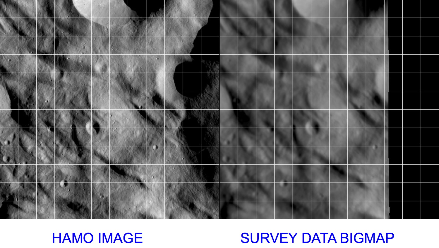
Update nominal file?: Usually enter 'n'. Rarely, you may want to set the nominal file equal to the .SUM solution. The following sample shows standard inputs and outputs from Here is a sample showing registering an image with a shape: This sample shows registering an image with a bigmap: 


